January 1st
2003 The fitting of the wheel assemblies into the chassis can be a little tricky. I found the easiest way (for me) was to place the washers and axle boxes on to the axle ends and then place the assembly into the frames, making sure the axle boxes slide into place. |
|
The motor mounting plates have slots that slide over the chassis cross brace/motor support, do not, at this stage, slide the motor mounts onto these, but rest them on top. I hope you can see what I mean, it was difficult to photograph. |
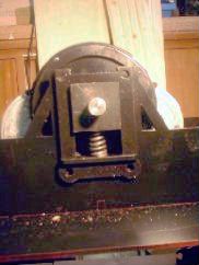
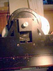 (2) (2)This places the axle box at the top (bottom?) of the chassis. Note the spigot in the bottom of the axle box slot. This 'pokes' thought the spring support and stops the spring sliding out. |
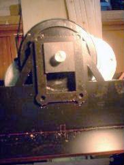 (3) (3)Now put the axle guides in place, the fixing holes will not line up with those in the chassis yet. (Make sure you have these the right way up!) |
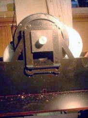 (4) (4)Next, I fitted the spring supports, again these will not slide down onto the spigot yet. |
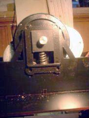 (5) (5)The spring should now slide into place. Repeat the process for the other side. |
 (6) (6)Holding a motor in each hand, carefully lift the assembly slightly then twist and drop into place. The spring supports should drop down over the spigots and the axle guides should line up with the bolt holes in the chassis. |
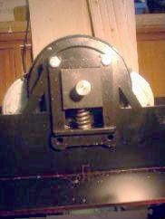 (7) (7)Put a nut and bolt in each side to keep everything together and check that the assembly is free to slide up and down against the springs. Things may be tight at the moment but will free up once the chassis has some running in. |
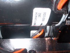
I tested the motors with the 12 volt battery
from Alice. I made a pair of leads with crocodile clips
one end for the battery terminals, and a large 'chocolate
block' connector on the other end. A switch was wired
into the 'live' wire so that I had some control over
things. I wired up each motor in turn to check they were all working ok, and then wired them up in pairs in series. The controller and batteries will be needed before I can proceed much further with the chassis. |
 (1)
(1)